THE SAND TABLE

How It Works
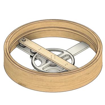
The sand table is a motorized zen garden that creates mesmerizing patterns by guiding a steel ball across the sand in circular motion. This is achieved using a magnet beneath the ball, mounted to a belt that moves back and forth on a long wooden arm. One end of the arm holds a motor; the other, a bearing. The entire arm assembly rotates via a large gear driven by a stepper motor with a 1:5 gear ratio. As the base spins and the belt shifts, the magnet traces complex paths. The mechanism is supported by a large bearing and enclosed in a wood-and-plastic housing. Designed for ease of assembly, the entire structure is held together with screws and can be built using a single hex wrench. An Arduino and motor controller manage the motor movements, allowing programmable patterns, while an internal LED strip adds a unique visual element. 2022–23

My role
This year-long school project was the most challenging build I had taken on at the time. I was responsible for all aspects of design, manufacturing, electronics, and testing, while a partner assisted with programming. It was my first time working with stepper motors, using screws in a full assembly, and running a CNC machine for part fabrication. The project pushed my skills across multiple areas and marked a major step forward in my design experience.

Pushing Limits Through Design
What began as a simple idea turned into a year-long challenge that tested my skills across design, electronics, and manufacturing. With over 80 custom parts and a drawer full of prototypes, this was the most complex and rewarding project I had taken on.

Humble beginnings
Every idea starts somewhere. When I began designing this project, my process looked very different from today. I started by creating a simple CAD model in just a few hours to prove the concept was possible. I also researched similar products to better understand the mechanisms and functionality behind them.

Designing From What I Know
With the proof of concept complete I started fresh with a new CAD document. The first part I designed was the bearing housing since the entire mechanism depended on it for support. From there the design naturally branched outward and everything was built around that one component. Looking back, it's wild how much grew from that single piece. Even now I often use that same approach starting with what I know then designing outward to solve what I do not.
Branching Out
As the design progressed, prototyping happened simultaneously. While I designed, parts were printing to avoid wasting time. The base was the first assembly, but it needed to be remade three times due to strength issues. As I added parts, the design evolved to accommodate changes. For example, the base legs were bent to make room for the motor instead of remaining flat
Early 3D Model Prototypes


CNC Machining
With the base roughly developed I focused on one of the most important components, the motor arm. It supports the top motor and belt, essentially controlling the entire system that allows the magnet to move back and forth. Fortunately, the manufacturing process went smoothly and I was able to get it right on the first try.
Measuring
To make sure everything fit correctly I relied heavily on caliper measurements. I recreated each physical component in the software as accurately as possible using those dimensions. This approach helped most parts fit properly on the first try.
Precision
Everything needed to function smoothly. Once key parts were installed, other components had to be adjusted to fit around them. For example, after installing the rail, which could not be moved, I designed and positioned the limit switch holders to align perfectly. These kinds of adjustments were necessary to avoid unwanted friction and ensuring durability.
Adapting Through Constraints
After constant prototyping the base was finally complete. Throughout the design and manufacturing process, if something didn’t work, I adapted the design on the fly. Working with tight clearances wasn’t easy, but by designing around a fixed housing size, I was able to anticipate many of these challenges early. Still, some changes were necessary, like lowering the bearing and entire assembly to fit under the enclosure. Thanks to the screw-based assembly and high part count, I could easily swap out individual pieces depending on how involved they were.
Breaking It Down to Build It Up
Manufacturing the rest of the body wasn’t easy. Due to the limitations with my 3D printer's build volume, I had to break the design into eight main pieces. Each one then needed to be carefully secured using screws and brackets. Despite doing this, the final frame turned out strong and rigid, as shown in this image.
Wiring It To Life
With the frame now installed, I began organizing and testing all the electrical components. Every motor controller and wire had to be carefully configured to work together. While this was a time-consuming process, it taught me a lot about what’s required to control these types of motors and bring the idea to life. I also had to work with unfamiliar components like a slip ring, a device that allows wires to rotate around a central bearing without tangling. These were parts I didn’t even know existed at the start and had to research and learn about along the way.
Transparent Engineering
I decided to go with an open and almost revealing body because I wanted people to truly appreciate and understand how much went into the internals. Additionally, as the motor arm moves by, it is visible, adding another cool element to the design. Because of this open design, everything needed to be polished including wire management, buttons, and internal housing.
A Low Friction Design
To help the ball move with minimal friction, I used a specific type of synthetic leather, attaching it to a thin circular sheet of wood. This disc sits directly on the frame and acts as the sand surface. To secure the leather to the wood, I used staples around the edge.

Finishing Touches
The final steps before adding the sand and LED strip involved installing risers to contain the sand and give the design a clean, finished look. Like the base, these risers had to be split into eight separate pieces and screwed directly into the frame. I originally planned to make them out of wood, but switched to 3D printing since CNC machining wouldn’t have been as efficient for the shapes and quantity needed.

One Year Later
After a year of work, the project finally came to an end. Throughout the process, I was constantly removing and reattaching components to make space and solve clearance issues. The final build truly reflects the complexity and ambition behind the design. While all of the components functioned as intended, programming issues prevented the table from fully operating. Still, it stands as a strong example of how far I can push a project in a short amount of time.
Controls
To operate the machine, I integrated a three-part control system: a central button acts as a pause function, the left switch toggles power (on/off), and the right switch manages the LED strip.
Everything In Its Place
This image shows how the transparent design reveals the tightly packed mechanism with everything nearly touching, yet running smooth.